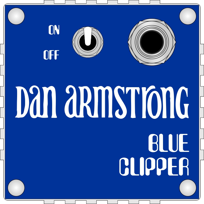
Today I repaired and traced this thing:

If you see one for sale, keep moving. This things is garbage, and not in a fun way.
I'll make a demo so you can hear it soon. But it really doesn't do much, so you're not missing out.

I was recently asked to repair one of these.
The traces on the board break easily, so I had to repair some of those, and after a while I got a nice filter sweep and some distortion. But it would always let through some clean signal even when the balance control was fully towards the fuzz side. Turns out an old battery leak had made one of the sides of that pot always have an extra 20k of resistance, while the other side worked like normal.
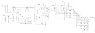
I traced the pedal and redrew the schematic that was on the inside.
I hope this can help someone else who wants to build or repair one of these.


I bought a 1966 Harmony Tenor guitar this week that I've started to fix up. It's missing the pickguard so I made a template based on the footprint of the old one and some pictures I found online. Now I'm just waiting for the pickguard material to show up.


I made a pattern and replaced the fake leather on my Yashica Electro 35 GT.


//Simple MIDI Drum Sequencer 1.0 by Åke Strömer
//July 27 2021
#include <MIDI.h>
MIDI_CREATE_DEFAULT_INSTANCE();
//----------- IN & OUTPUTS ----------
//-------------MatrixMux-------------
#define clockPin 3 //Pin connected to RCLK/SH_CP/SHIFT REGISTER CLOCK pin 11 of 74HC595
#define latchPin 4 //Pin connected to SRCLK/ST_CP/OUTPUT REGISTER CLOCK pin 12 of 74HC595
#define dataPin 5 //Pin connected to SER/DS/INPUT pin 14 of 74HC595
//---------Knobs and Switches--------
#define clk 2
uint8_t SwRow[4] = {6, 7, 8, 9};
#define shiftSw 10
#define resetSw 11
uint8_t seqLength = 17;
uint8_t trackNr = 0;
//------------ MIDI -----------------
// 808 BD SD LT MT HT MA RS CB HH OH
// 0 1 2 3 4 5 6 7 8 9 10 11 12 13 14 15
uint8_t note[16] = {36, 38, 40, 41, 43, 39, 37, 56, 42, 46, 48, 50, 52, 54, 56, 58};
uint8_t midiCh = 1;
bool clkProgress = LOW;
uint8_t editMode = 0;
uint8_t stepNr = 0;
uint8_t seqNr;
uint8_t scanStep = 0;
bool dispStep[17] = {0, 0, 0, 0, 0, 0, 0, 0, 0, 0, 0, 0, 0, 0, 0, 0};
// [TRACK][STEP]
bool currentSeq[16][17] =
{
// 0 1 2 3 4 5 6 7 8 9 10 11 12 13 14 15 16 SEQUENCE NR 0
{0, 1, 0, 0, 0, 1, 0, 0, 0, 1, 0, 0, 0, 1, 0, 0, 0},
{0, 0, 0, 0, 0, 0, 0, 0, 0, 0, 0, 0, 0, 0, 0, 0, 0},
{0, 0, 0, 0, 0, 0, 0, 0, 0, 0, 0, 0, 0, 0, 0, 0, 0},
{0, 0, 0, 0, 0, 0, 0, 0, 0, 0, 0, 0, 0, 0, 0, 0, 0},
{0, 0, 0, 0, 0, 0, 0, 0, 0, 0, 0, 0, 0, 0, 0, 0, 0},
{0, 0, 0, 0, 0, 0, 0, 0, 0, 0, 0, 0, 0, 0, 0, 0, 0},
{0, 0, 0, 0, 0, 0, 0, 0, 0, 0, 0, 0, 0, 0, 0, 0, 0},
{0, 0, 0, 0, 0, 0, 0, 0, 0, 0, 0, 0, 0, 0, 0, 0, 0},
{0, 0, 0, 0, 0, 0, 0, 0, 0, 0, 0, 0, 0, 0, 0, 0, 0},
{0, 0, 0, 0, 0, 0, 0, 0, 0, 0, 0, 0, 0, 0, 0, 0, 0},
{0, 0, 0, 0, 0, 0, 0, 0, 0, 0, 0, 0, 0, 0, 0, 0, 0},
{0, 0, 0, 0, 0, 0, 0, 0, 0, 0, 0, 0, 0, 0, 0, 0, 0},
{0, 0, 0, 0, 0, 0, 0, 0, 0, 0, 0, 0, 0, 0, 0, 0, 0},
{0, 0, 0, 0, 0, 0, 0, 0, 0, 0, 0, 0, 0, 0, 0, 0, 0},
{0, 0, 0, 0, 0, 0, 0, 0, 0, 0, 0, 0, 0, 0, 0, 0, 0},
{0, 0, 0, 0, 0, 0, 0, 0, 0, 0, 0, 0, 0, 0, 0, 0, 0}
};
bool resetState = 0;
bool shiftState = 0;
bool lastShiftState = 0;
long time = 0;
long debounce = 300;
void setup()
{
MIDI.begin(midiCh);
for (uint8_t i = 0; i < 4; i++)
{
pinMode(SwRow[i], INPUT);
}
pinMode(latchPin, OUTPUT);
pinMode(clockPin, OUTPUT);
pinMode(dataPin, OUTPUT);
pinMode(shiftSw, INPUT_PULLUP);
pinMode(resetSw, INPUT_PULLUP);
seqNr = 0;
attachInterrupt(digitalPinToInterrupt(clk), isr, RISING);
}
void loop()
{
mux();
readButtons();
if (clkProgress == HIGH)
{
stepNr++;
clkProgress = LOW;
for (uint8_t i = 0; i < 10; i++)
{
if (currentSeq[i][stepNr] == 1)
{
MIDINoteOn(i);
}
}
}
if (stepNr >= 16)
{
stepNr = 0;
}
for (int i = 0; i < 17; i++)
{
dispStep[i] = 0;
}
if (editMode == 1)
{
dispStep[trackNr+1] = 1;
}
if (editMode == 2)
{
dispStep[midiCh] = 1;
}
}
void readButtons()
{
shiftState = digitalRead(shiftSw);
resetState = digitalRead(resetSw);
if (resetState == LOW && shiftState == HIGH)
{
stepNr = 0;
}
else if (resetState == HIGH && shiftState == LOW)
{
editMode = 1;
}
else if (resetState == LOW && shiftState == LOW)
{
editMode = 2;
}
else
{
editMode = 0;
}
}
void MIDINoteOn(uint8_t noteNr)
{
switch (noteNr)
{
case 0:
MIDI.sendNoteOn(note[0], 127, midiCh);
MIDI.sendNoteOff(note[0], 127, midiCh);
break;
case 1:
MIDI.sendNoteOn(note[1], 127, midiCh);
MIDI.sendNoteOff(note[1], 127, midiCh);
break;
case 2:
MIDI.sendNoteOn(note[2], 127, midiCh);
MIDI.sendNoteOff(note[2], 127, midiCh);
break;
case 3:
MIDI.sendNoteOn(note[3], 127, midiCh);
MIDI.sendNoteOff(note[3], 127, midiCh);
break;
case 4:
MIDI.sendNoteOn(note[4], 127, midiCh);
MIDI.sendNoteOff(note[4], 127, midiCh);
break;
case 5:
MIDI.sendNoteOn(note[5], 127, midiCh);
MIDI.sendNoteOff(note[5], 127, midiCh);
break;
case 6:
MIDI.sendNoteOn(note[6], 127, midiCh);
MIDI.sendNoteOff(note[6], 127, midiCh);
break;
case 7:
MIDI.sendNoteOn(note[7], 127, midiCh);
MIDI.sendNoteOff(note[7], 127, midiCh);
break;
case 8:
MIDI.sendNoteOn(note[8], 127, midiCh);
MIDI.sendNoteOff(note[8], 127, midiCh);
break;
case 9:
MIDI.sendNoteOn(note[9], 127, midiCh);
MIDI.sendNoteOff(note[9], 127, midiCh);
break;
case 10:
MIDI.sendNoteOn(note[10], 127, midiCh);
MIDI.sendNoteOff(note[10], 127, midiCh);
break;
case 11:
MIDI.sendNoteOn(note[11], 127, midiCh);
MIDI.sendNoteOff(note[11], 127, midiCh);
break;
case 12:
MIDI.sendNoteOn(note[12], 127, midiCh);
MIDI.sendNoteOff(note[12], 127, midiCh);
break;
case 13:
MIDI.sendNoteOn(note[13], 127, midiCh);
MIDI.sendNoteOff(note[13], 127, midiCh);
break;
case 14:
MIDI.sendNoteOn(note[14], 127, midiCh);
MIDI.sendNoteOff(note[14], 127, midiCh);
break;
case 15:
MIDI.sendNoteOn(note[15], 127, midiCh);
MIDI.sendNoteOff(note[15], 127, midiCh);
break;
default:
break;
}
}
void mux()
{
uint8_t dataToSend;
bool swRead[4] = {0, 0, 0, 0};
for (uint8_t x = 0; x < 4; x++) //Column Scanning
{
dataToSend = (16 << x);
digitalWrite(latchPin, LOW);
shiftOut(dataPin, clockPin, LSBFIRST, dataToSend);
digitalWrite(latchPin, HIGH);
//------------ READ SWITCHES -----------------
for (uint8_t ySw = 0; ySw < 4; ySw++)
{
swRead[ySw] = digitalRead(SwRow[ySw]);
if (swRead[ySw] == HIGH && millis() - time > debounce)
{
uint8_t swStep = 1 + x + 4 * ySw;
if (editMode == 0) //WRITE MODE
{
if (currentSeq[trackNr][swStep] == 0)
{
currentSeq[trackNr][swStep] = 1;
}
else
{
currentSeq[trackNr][swStep] = 0;
}
}
if (editMode == 1) //TRACK NR MODE
{
trackNr = swStep - 1;
}
if (editMode == 2) //MIDI Ch Mode
{
midiCh = swStep;
}
time = millis();
}
}
//------------ LED'S -----------------
for (uint8_t y = 0; y < 4; y++) //Row Scanning
{
bool thisLED;
int scanStep = y + 1 + x * 4; //Fast matrix scan
if (editMode == 1) //TRACK NR MODE
{
thisLED = dispStep[scanStep];
}
else if (editMode == 2) //MIDI Ch Mode
{
thisLED = dispStep[scanStep];
}
else
{
thisLED = currentSeq[trackNr][scanStep];
}
if (stepNr + 1 == scanStep)
{
(thisLED) ? thisLED = 0 : thisLED = 1;
}
(thisLED == 0) ? dataToSend = B00000000 : dataToSend = (16 << y) | (1 << x);
digitalWrite(latchPin, LOW);
shiftOut(dataPin, clockPin, LSBFIRST, dataToSend);
digitalWrite(latchPin, HIGH);
}
}
}
void isr()
{
clkProgress = HIGH;
}


I also made some drawings of Nils Olof Carlin's phaser based on pictures I found at moodysounds & the effects database.